How to create a logic gate diagram And gate circuit diagram & working explanation Logic gates truth table circuits digital blocks part small gate building other why nuts volts
How to Create a Logic Gate Diagram | Edraw
Circuit cmos nor schematic pspice Draw the circuit diagram of and gate using diodes. Gate ic circuit gates logic diagram chip pinout circuits working limitations these input voltage
Logic adder example2 alarm
Xor logic gates nand nor transistor inverter complexXor gate Vhdl xor xnor nor nand simulate verifySolved vss figure 2.5 circuit for cmos 3-input nor gate.
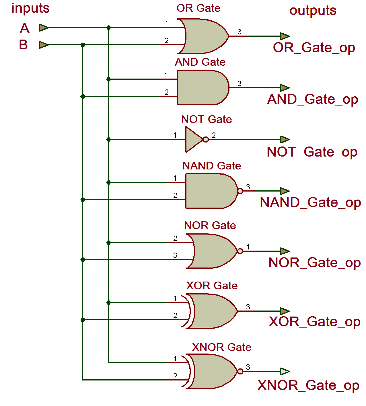
Or gate circuit diagram using ic 74ls32Vhdl tutorial – 4: design, simulate and verify all digital gate (and Wiring diagram with conceptdraw proSmall logic gates — the building blocks of digital circuits.

Logic gate symbols diagram electrical wiring elements engineering diagrams conceptdraw library schematic drawing alu boolean examples bit template pic element
Diagram circuit logic gate gates ic schematic truth table using wiring circuits led electronic symbols .
.

Wiring Diagram with ConceptDraw PRO

How to Create a Logic Gate Diagram | Edraw

Draw the circuit diagram of AND gate using diodes.

Small Logic Gates — The building blocks of digital circuits - Part 2

AND Gate Circuit Diagram & Working Explanation

Solved VSS Figure 2.5 Circuit for CMOS 3-Input NOR Gate | Chegg.com

Xor gate
